

Interactions
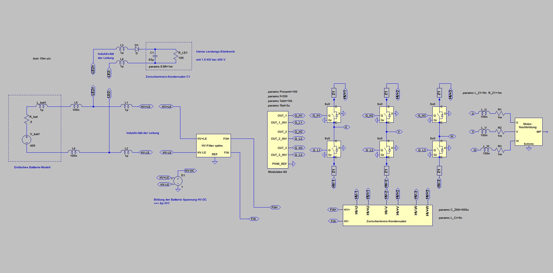
Simulation of the Rippel-Current through capacitor C1 with Diode in series
Despite the resonance condition, the capacitor current is only a fraction of the current without diode (RMS = 162 A see effects).
However, the diode causes a voltage drop and has to be cooled correspondingly at higher power.
Switching on causes a current surge through the diode and must therefore not take place arbitrarily fast - or requires a high surge current capability of the diode
Rapid voltage changes in the electrical system, especially in emergency shutdown, create a negative voltage at the diode, which should be limited by appropriate circuitry, otherwise an expensive diode with high voltage and higher power loss has to be used
In addition, the diode must meet all EMC requirements (e.g. ESD or BCI etc.) and should therefore be protected by appropriate circuitry
Of course, a diode is not suitable for all applications: If the current should also flow in the opposite direction, such as with DCDC converters, more complex active change-overs are required
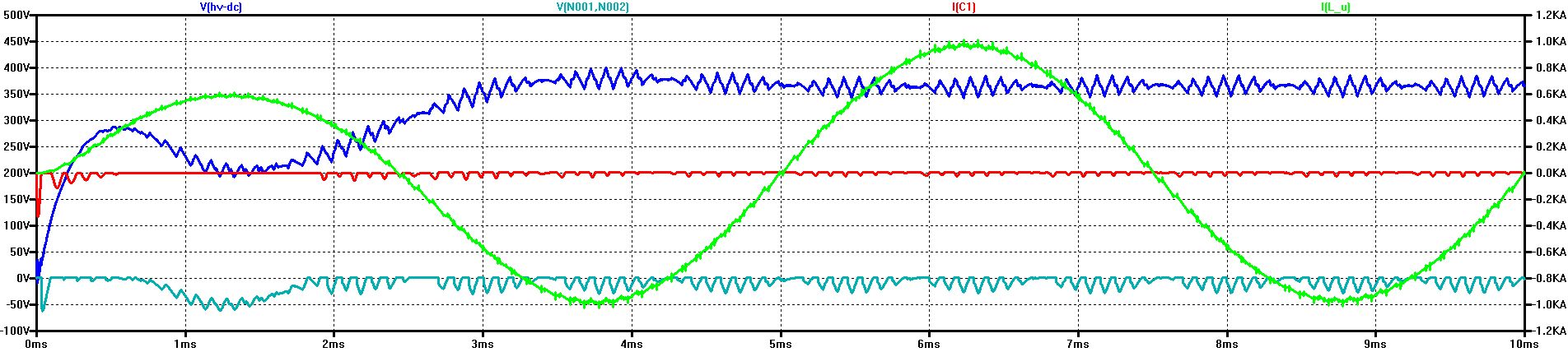
Red: Ripple-Current at capacitor C1 (RMS = 7.2 A) Blue: Ripple-Voltage Turquoise: voltage at the Diode Green: Phase-Current
Countermeasures
The chapters Ripple-Voltage, Spectrum and Effects have dealt with the relationships and the threatening interactions between large inverters and small electronics
The Ripple-Voltages of large inverters are a significant stress for smaller electronics when the DC link capacitors of the smaller electronics resonate with the Ripple-Voltage. In this case, a Ripple-Current higher by factors is generated in the smaller DC link capacitor, which can clearly exceed the normal own Ripple-Current - and thus can lead to overloading and damage and failure.
The resonance frequency results from the capacitance of the DC link capacitor and all differential mode inductances between the Ripple-Voltage source (the large inverter) and the small electronics. These inductances include both the line inductances and the filter inductances. Not included are the common-mode inductances of lines and filters.
Particularly dangerous is the range of the switching frequency + - the 6-fold rotational frequency, because here the spectrum of the ripple voltage has the highest amplitudes.
Not only the excessive Ripple-Current represents a danger for the smaller electronics - also the Ripple-Voltage at its intermediate circuit can increase dramatically at resonance and thus cause a failure by overvoltage.
When performing Ripple-Voltage tests, particular attention must be given to the internal resistance of the test generator: if the internal resistance is too small, the test object will be unnecessarily stressed - too high an internal resistance makes testing too easy.
What countermeasures can be taken in the design of on-board systems, cables and the components of the modules involved ?
Keep the resonance frequency out of the range of the main excitation
Keep the differential mode inductances in the filters and in the lines so small that the resonance frequency together with the DC link capacitors ends up as far above the clock frequency of the large inverters as possible.
This may also mean using shielded wires instead of unshielded wires, as the inductance of shielded wires is significantly (factor 10 or more) below the inductance of unshielded wires.
Provide increased Ripple-Current capacity of the DC link capacitors
Dimension the DC link capacitors for the greatly increased Ripple-Current load
Damping of the resonances
Damp the resonance by means of resistors in parallel or in series to the capacitances and inductance
Diodes
Switch a diode as a rectifier in front of the DC link
Acts very effectively against the resonance (see simulation below)
A disadvantage is the power loss in the diode and the necessary additional circuitry against excessive negative voltage
Another disadvantage is the limitation of the power flow in one direction
Active measures
Switches or diodes together with switches to reduce power dissipation and/or along with changeover switches to change the power flow direction
Advantages: Less power loss, change of power flow direction
Disadvantages: Complexity, complicated (error-prone) switching logic, protection against interference, transients, ESD, BCI etc. necessary
We are happy to help with the analysis of the situation and the selection and design of the optimal measures
© Ingenieurbüro Lindenberger 8447