

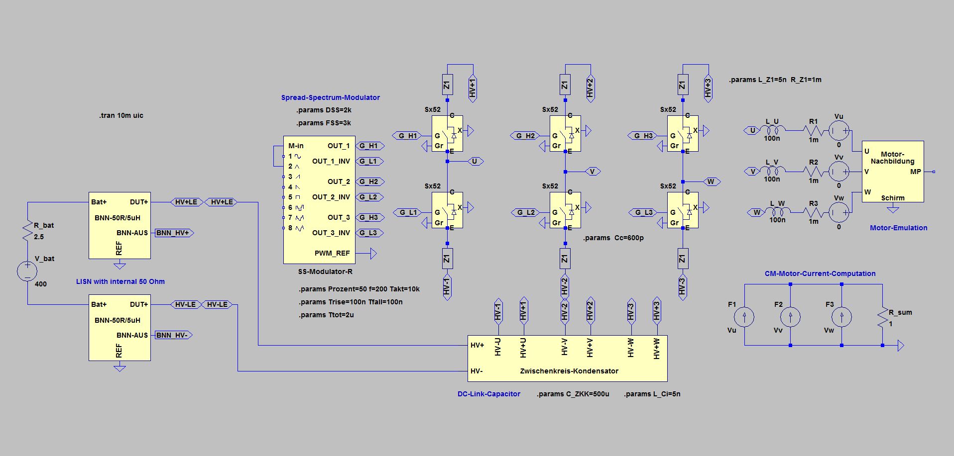
Spread-Spectrum with Inverters

Simple inverter circuit with fixed clocking (Takt = 10 kHz, DSS = 0 kHz)
The picture shows a simple inverter circuit with fixed clocking (Takt = 10 kHz, DSS = 0 kHz). Simple means here, that all filter elements have been omitted - on the one hand, in order to make the circuit and the behavior as clear as possible, on the other hand, in order to obtain sufficiently large disturbances to get no problem with the dynamic range of the FFT.
While the modulator depicted is actually intended for spread spectrum modulation, it can also operate with fixed timing if DSS is set to 0k or if M-in is left open (analogous to the spread spectrum modulator on the booster circuit ).
The fixed clock inverter is the comparison reference for the circuits with spread spectrum modulation.
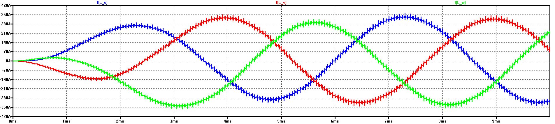
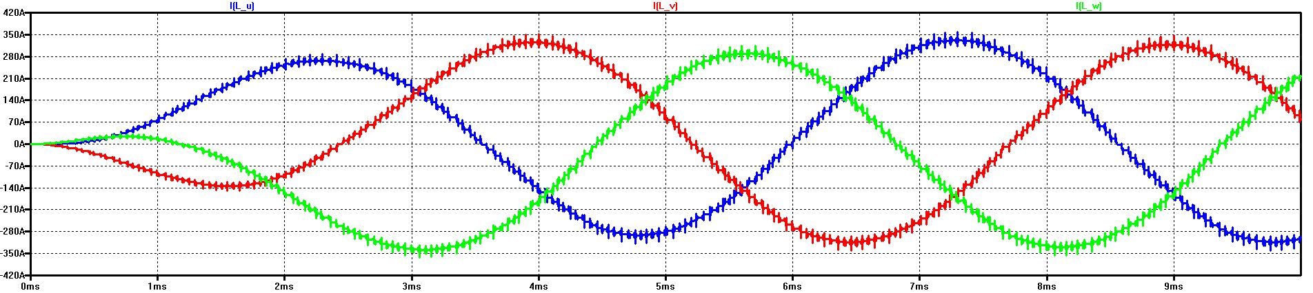
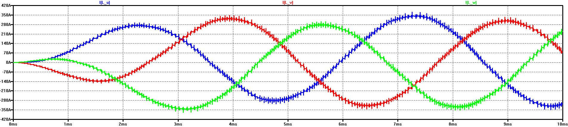
The diagram shows the start-up of the current in the 3 phases
After about 3 ms, a sufficiently steady state has been reached (the internal resistance of the HV voltage has been selected to be particularly high for this)

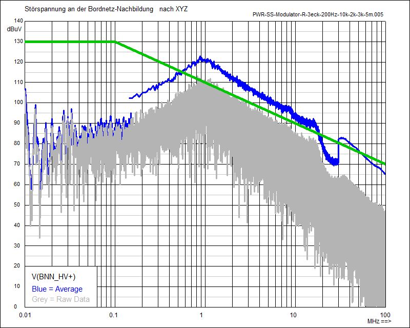
Noise Spectrum with fixed clock (10 kHz) at BNN (HV+)
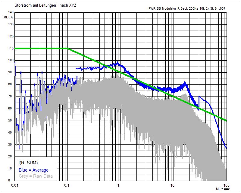
CM Spectrum of the Phase Currents with fixed clock (10 kHz)
Start-up of the current in the 3 phases with Spread-Spectrum Modulation (Triangular Modulation, Delta-Frequency DSS = 2 kHz)
Compared to the phase current at a fixed clock, no significant difference in the current profile can be seen.
Following shown are the noise spectra with Triangular Shift of the clock, with Fixed Clock and with Random Shift:
Noise Spectrum with Triangular Modulation (2 kHz) at BNN (HV+)
CM Spectrum of the Phase Currents with Triangular Modulation (2 kHz)
Noise Spectrum with fixed clock (10 kHz) at BNN (HV+)
CM Spectrum of the Phase Currents with fixed clock (10 kHz)
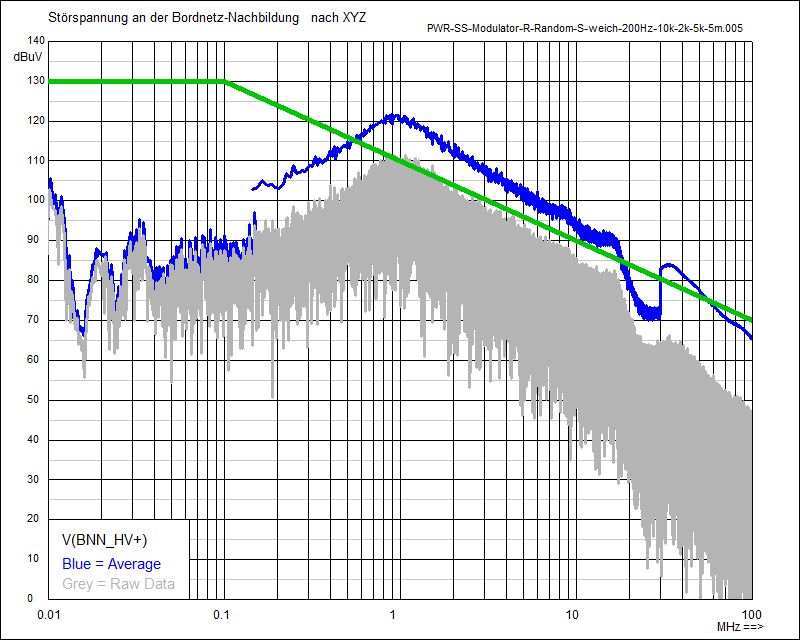
Noise Spectrum with Random Modulation (2 kHz) at BNN (HV+)
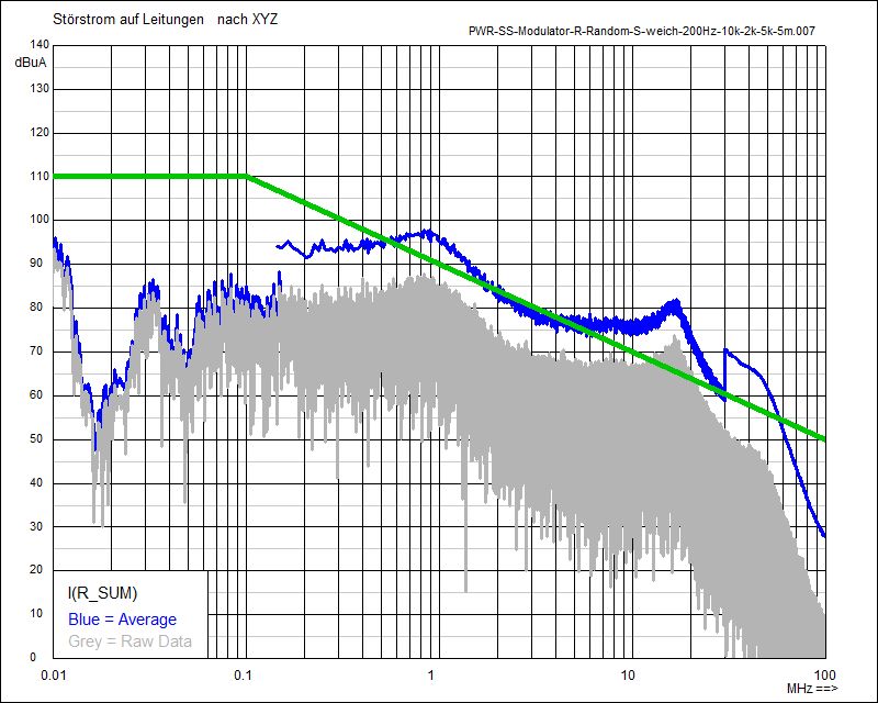
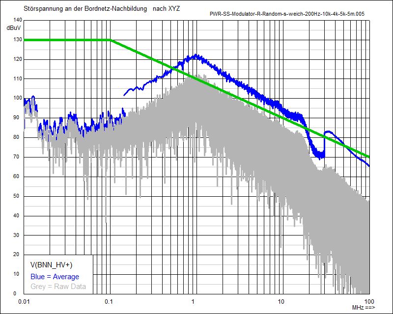
CM Spectrum of the Phase Currents with Random Modulation (2 kHz)
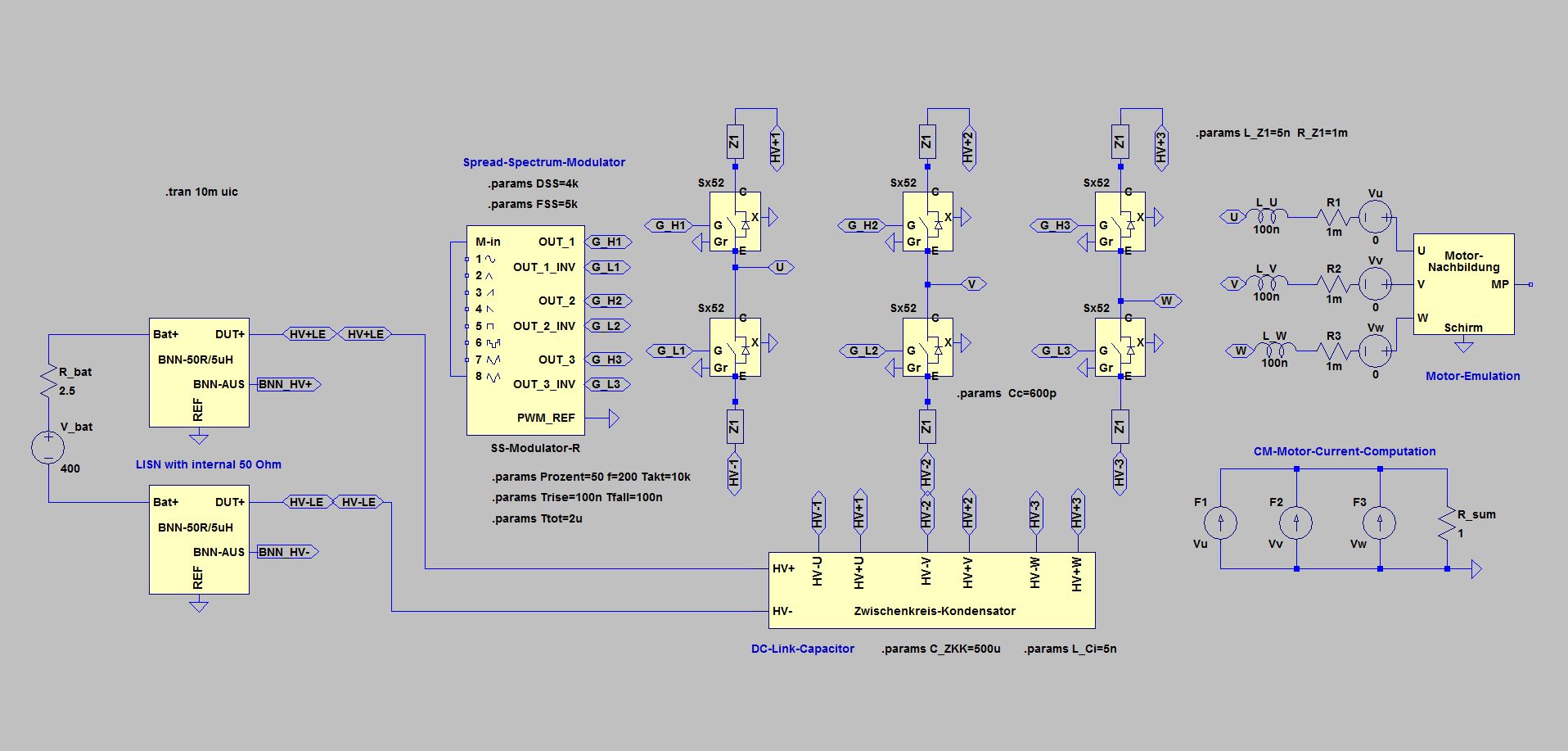
Noise Spectrum with Random Modulation (4 kHz) at BNN (HV+)
CM Spectrum of the Phase Currents with Random Modulation (4 kHz)
Noise Spectrum with fixed clock (10 kHz) at BNN (HV+)
CM Spectrum of the Phase Currents with fixed clock (10 kHz)
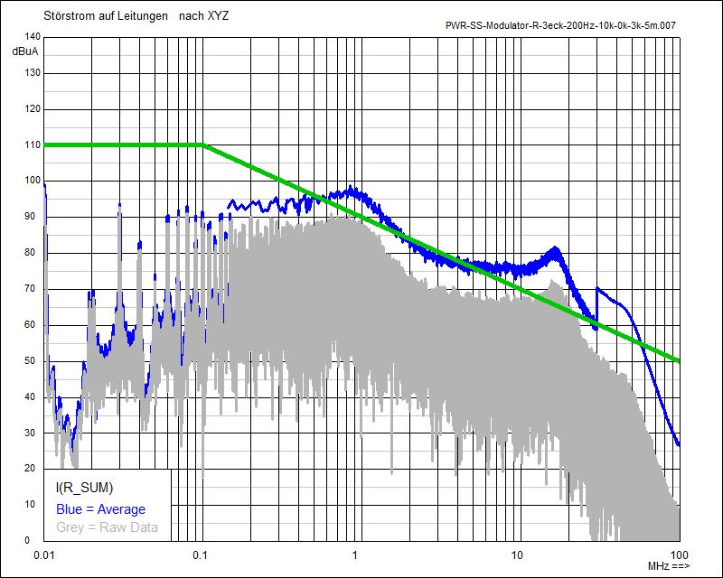
The spectra are typical for inverters without filter circuits at intermediate-level. Below 150 kHz, the individual spectral lines are resolved even after processing by the average detector (200 Hz bandwidth). Above 150 kHz, the blue envelope gets largely smooth after the average detector (10 kHz bandwidth), from 30 MHz on then completely (120 kHz bandwidth).
The Common-Mode Spectrum (CM) of the phase currents is similar to the spectrum on the HV-DC side. The current circuit for the switching spikes is closed via the capacitors in the artificial networks (BNN = LISN) to ground and the winding capacities of the motor emulation to ground.
The green limit curves serve only for better orientation and easier comparison.
Simple inverter circuit with Triangular Modulation (DSS = 2 kHz)
The Spread-Spectrum-Modulator is working here with Triangular Modulation and 2 kHz frequency shift of the clock - from 8 kHz to 12 kHz
The change of the frequency shifting is done with 3 kHz (FSS = 3k)
A clear reduction of noise levels only results below 150 kHz. With random modulation, the improvement is about 5 to 10 dB.
Above 150 kHz, the amplitudes of the individual spectral lines are reduced (gray) - but the level after the average detector (blue) remains largely the same.
With a measurement bandwidth of 10 kHz, simply the free gaps between two adjacent spectral lines are missing. The frequency shifting results in overlapping areas - and thus no reduction after the summation in the measurement window.
Simple inverter circuit with Random Modulation (DSS = 4 kHz)
The Spread-Spectrum-Modulator is working here with Random Modulation and 4 kHz frequency shift of the clock - from 8 kHz to 12 kHz
The change of the frequency shifting is done with 5 kHz (FSS = 5k)
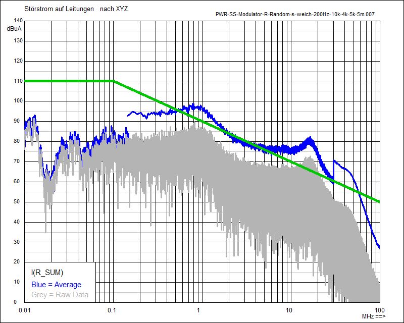
Start-up of the current in the 3 phases with Spread-Spectrum Modulation (Random Modulation, Delta-Frequency DSS = 4 kHz)
Compared to the phase current at a fixed clock, the change in the distribution of switching actions is clearly visible.
Following shown are the noise spectra with Triangular Shift of the Clock, with Fixed Clock and with Random Shift:
As with the modulation at 2 kHz, a clear reduction of noise levels results only below 150 kHz. Compared to the 2 kHz modulation, the 4 kHz noise level is further reduced at the lowest harmonics (10 kHz to 40 kHz).
Above 150 kHz, there is no particular difference to the modulation at 2 kHz.
© Ingenieurbüro Lindenberger 8447