

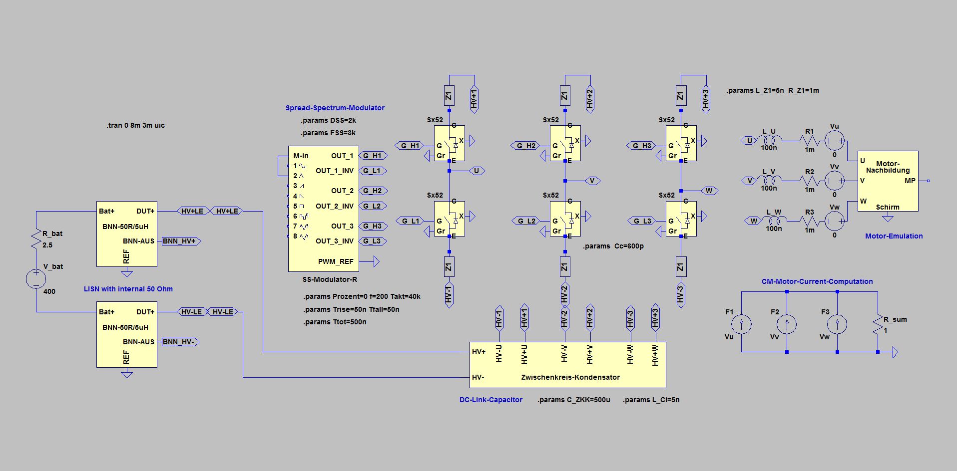
Spread-Spectrum with Inverters
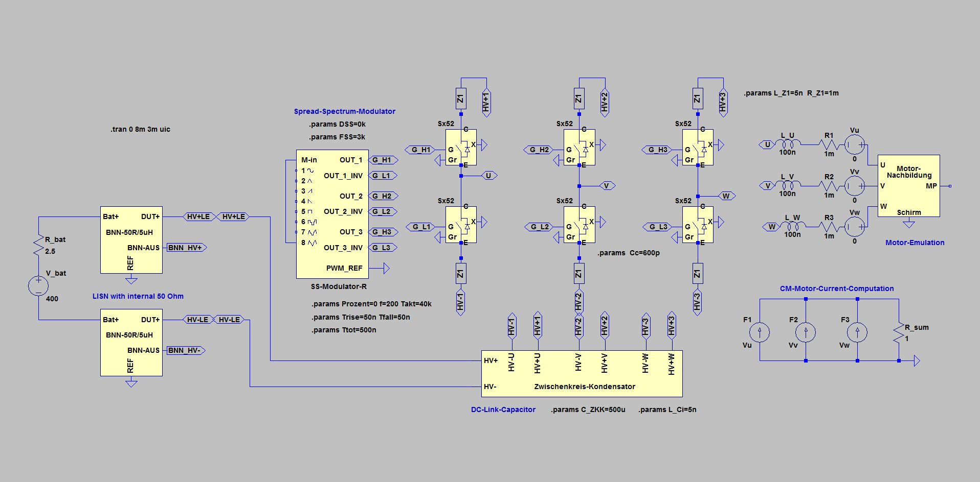
Simple inverter circuit with 40 kHz switching frequency (Takt = 40 kHz, DSS = 0 kHz) Zero-Vector
The effect of the Spread-Spectrum-Modulation can be demonstrated particularly clearly in the Zero-Vector-Mode of the inverter:
In Zero-Vector-Mode, all 3 half-bridges of the inverter switch in the same direction at the same time in the rhythm of the clock frequency. This is a very significant difference to normal operation, where the switching points of the half bridges constantly shift to approximate the known sinusoidal current curve. Of course, this modulation for generating the sinusoidal motor current partly obscures the additional Spread-Spectrum-Modulation. In Zero-Vector-Mode, this type of modulation is now missing, so that the effect of the Spread-Spectrum-Modulation appears more clearly.
As with the simulations before, the inverter with a fixed clock again serves as a comparison reference.
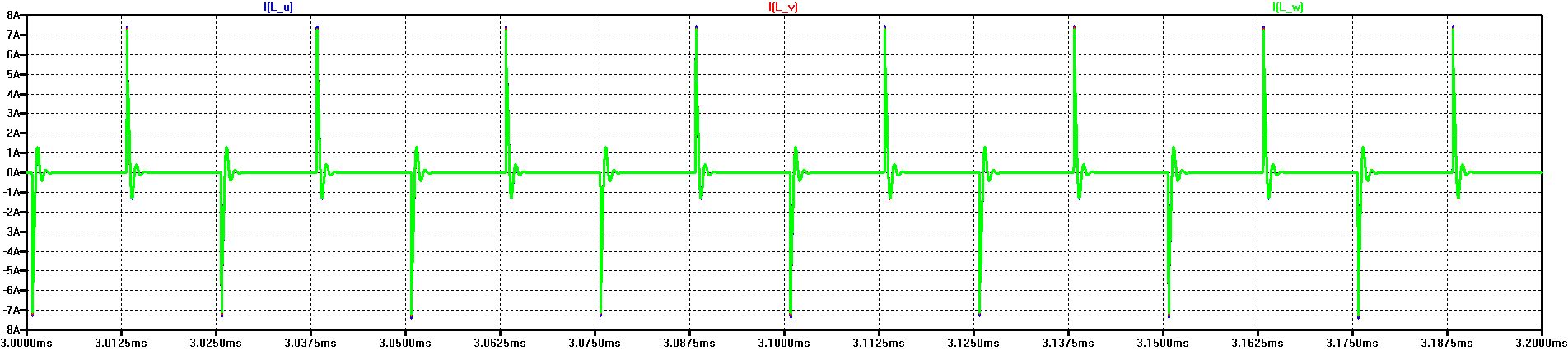
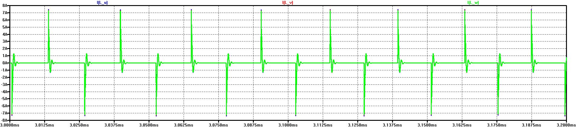
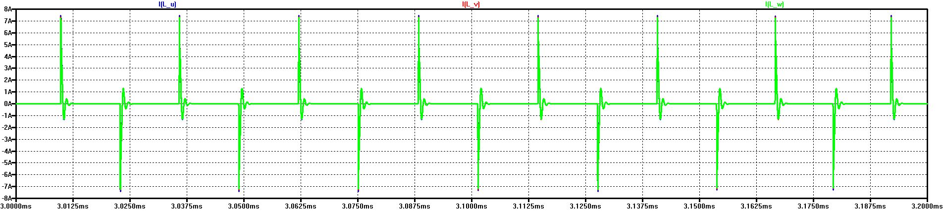
The diagram shows the start-up of the current in the 3 phases during Zero-Vector-Operation
According to the clock frequency of 40 kHz, occurs a switching action to HV+ or HV- every 12.5 μs at the same time in each half-bridge.
This creates a current spike in the positive and the negative direction - on the one hand because of the parasitic capacitances to the ground in the motor windings and the switches themselves - on the other hand because of the measuring impedance to ground in the artificial networks (BNN/LISN).
The switching operations are so uniform that the curves almost completely overlap and only the last displayed green curve of phase W remains clearly visible. Without drive modulation, the motor current remains at 0 A on average (except for the spikes).
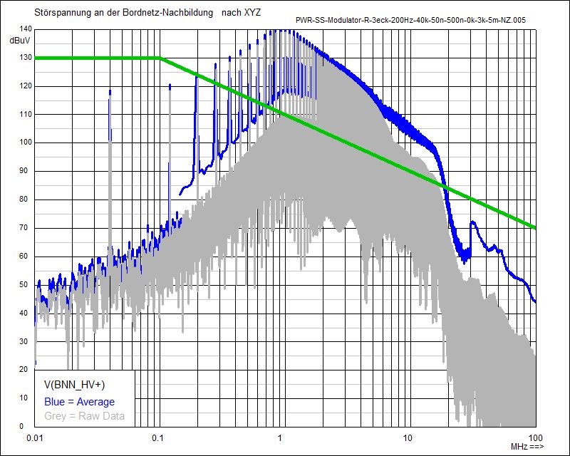
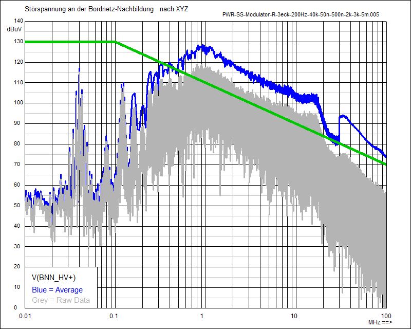
Noise Spectrum Zero-Vector with fixed clock (40 kHz) at BNN (HV+)
The current in the 3 phases with Spread-Spectrum Modulation (Triangular Modulation, Delta-Frequency DSS = 2 kHz) Zero-Vector
In comparison to the phase current at a fixed clock, the shift of the switching times and thus of the spikes is clearly visible.
In the diagram section, the switching period is initially extended and then shortened again.
Following shown are the noise spectra with Triangular Shift of the Clock, with Fixed Clock and with Random Shift for Zero-Vector (ZV) and 50%
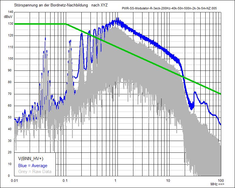
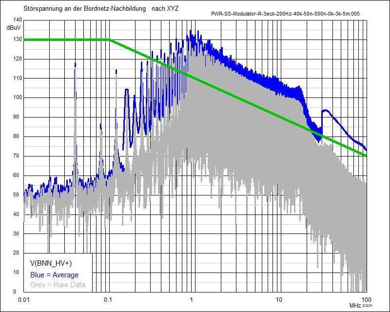
Noise Spectrum ZV with Triangular Modulation (2 kHz) at BNN (HV+)
Noise Spectrum Zero-Vector with fixed clock (40 kHz) at BNN (HV+)
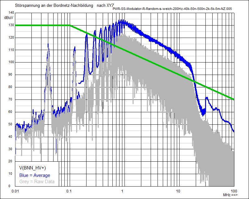
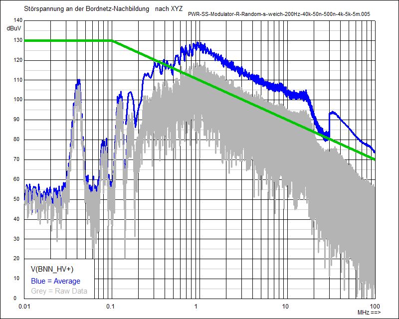
Noise Spectrum ZV with Random Modulation (2 kHz) at BNN (HV+)
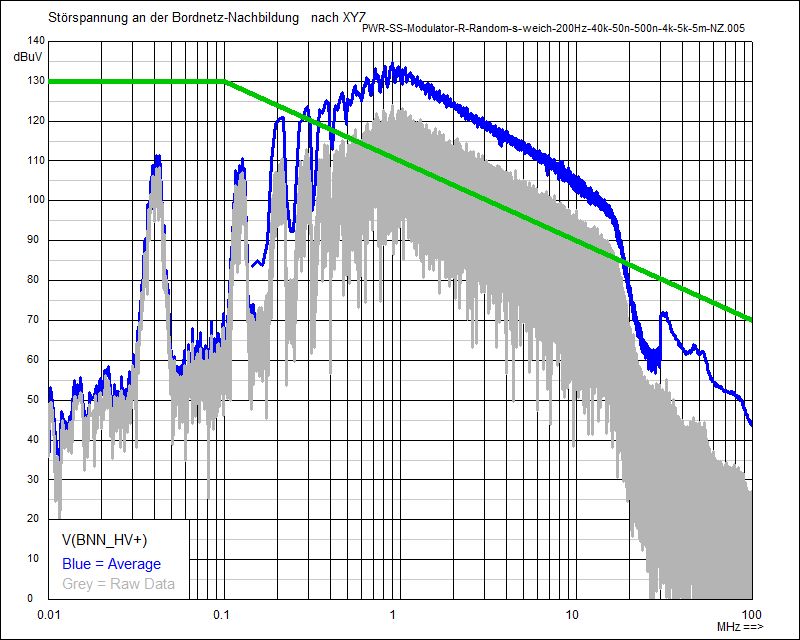
Noise Spectrum ZV with Random Modulation (4 kHz) at BNN (HV+)
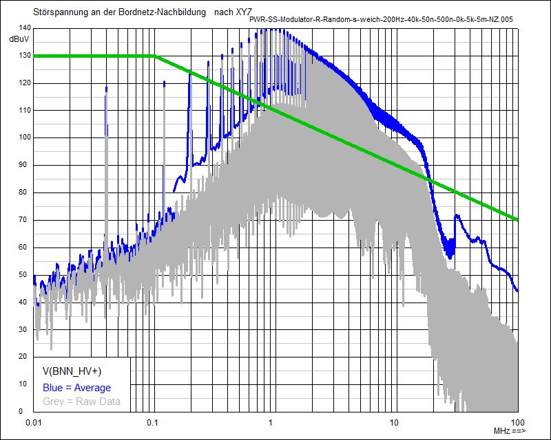
Noise Spectrum ZV with fixed clock (40 kHz) at BNN (HV+)
When operating with a Zero-Vector, the interference spectrum has only the odd harmonics, the even ones are missing. As a result, the distance between adjacent spectral lines is twice as large as with 50% modulation. By simultaneously switching all 3 half-bridges, the noise level for low frequencies increases by about 6 dB. For high frequencies, however, the noise level is reduced, because the switching operation takes place without current switching (there is no motor current).
Here too, the green limit lines serve only for better orientation and for easier comparison..
Simple inverter circuit (40 kHz clock) with Triangular Modulation (DSS = 2 kHz) Zero-Vector
The Spread-Spectrum-Modulator is working here with Triangular Modulation and 2 kHz frequency shift of the clock - from 38 kHz to 42 kHz
The change of the frequency shifting is done with 3 kHz (FSS = 3k)
In the direct comparison between the operation with Zero-Vector (left diagrams) and the operation with 50% modulation (right diagrams), the larger distance of the spectral lines with Zero-Vector is clearly visible.
Due to the wider spread of the spectral lines, overlapping areas, caused by the frequency shift of the Spread-Spectrum-Modulation, are less.
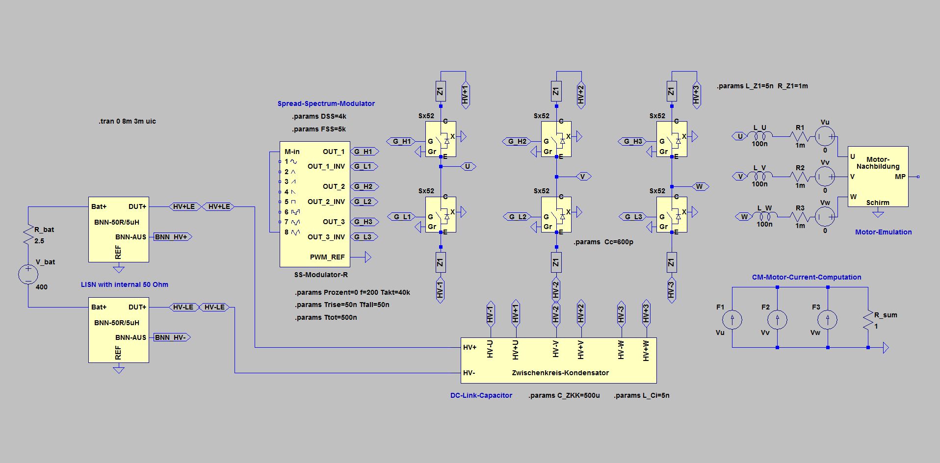
Simple inverter circuit (40 kHz clock) with Random Modulation (DSS = 4 kHz) Zero-Vector
The Spread-Spectrum-Modulator is working here with Random Modulation and 4 kHz frequency shift of the clock - from 36 kHz to 44 kHz
The change of the frequency shifting is done with 5 kHz (FSS = 5k)
The current in the 3 phases with Spread-Spectrum Modulation (Random Modulation, Delta-Frequency DSS = 4 kHz) Zero-Vector
In comparison to the phase current at a fixed clock, the shift of the switching times and thus of the spikes is clearly visible. Random modulation does not produce a fixed pattern, but a stochastic shift, which, in contrast to triangular modulation, does not produce additional spectrum lines, but rather an envelope curve.
Following shown are the noise spectra with Random Shift of the Clock and with Fixed Clock for Zero-Vector (ZV) and 50%
Compared to the modulation with 2 kHz, the noise level with 4 kHz is reduced a little further in the lower frequency range up to 500 kHz
Above 500 kHz, the larger shift results in a somewhat smoother course.
CM Spectrum Zero-Vector of the Phase Currents with fixed clock (40 kHz)
Noise Spectrum 50% with Triangular Modulation (2 kHz) at BNN (HV+)
Noise Spectrum 50% with fixed clock (40 kHz) at BNN (HV+)
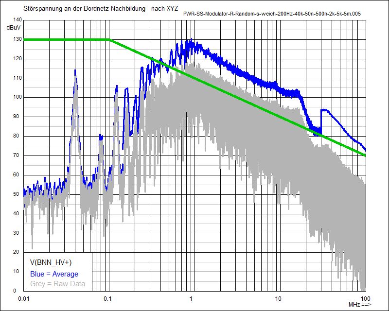
Noise Spectrum 50% with Random Modulation (2 kHz) at BNN (HV+)
Noise Spectrum 50% with Random Modulation (4 kHz) at BNN (HV+)
Noise Spectrum 50% with fixed clock (40 kHz) at BNN (HV+)
© Ingenieurbüro Lindenberger 8447