

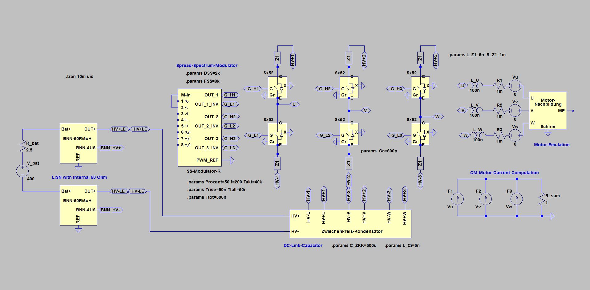
Spread-Spectrum with Inverters
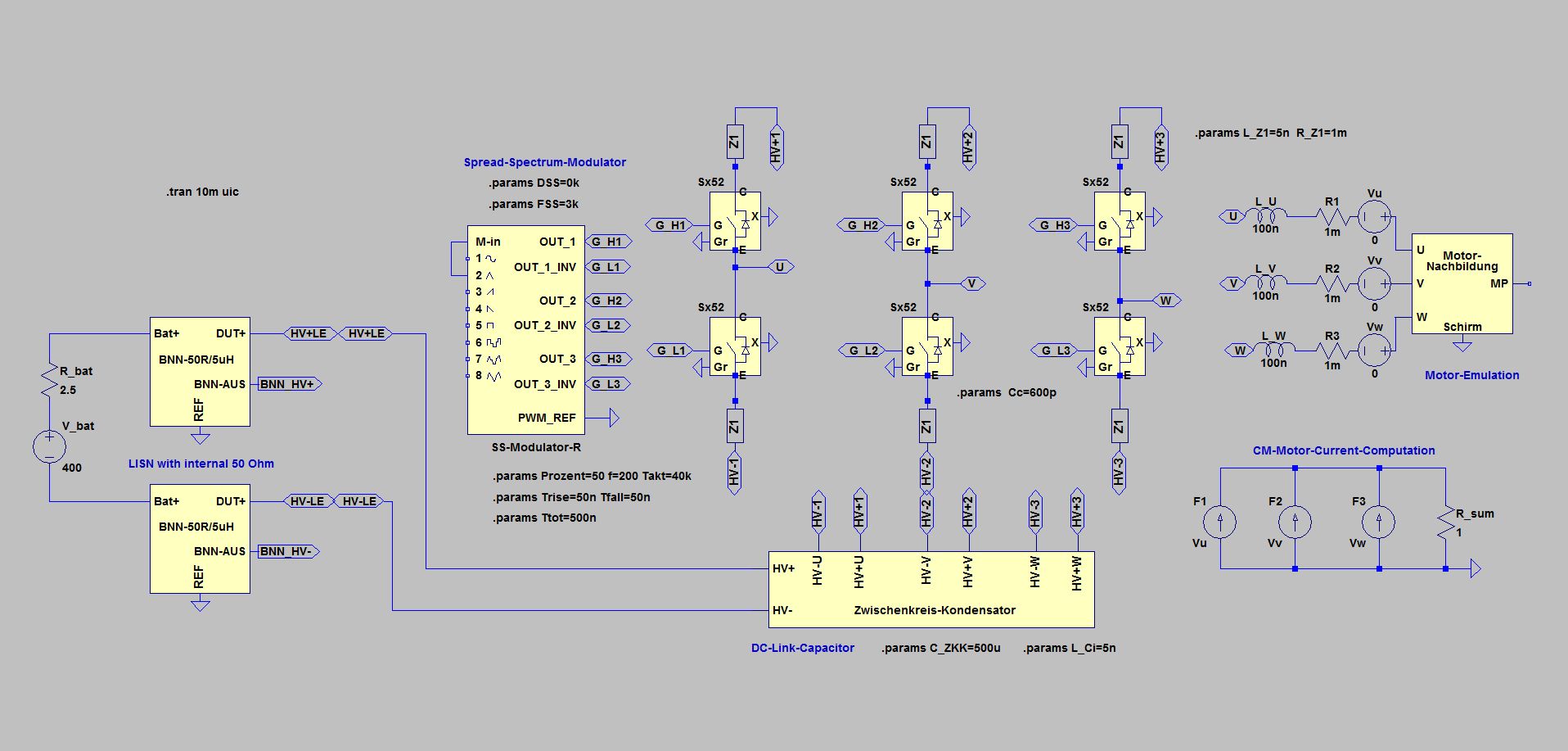
Simple inverter circuit with 40 kHz switching frequency (Takt = 40 kHz, DSS = 0 kHz)
In the inverter with 10 kHz clock frequency, the Spread-Spectrum-Modulation had given no significant improvement above 150 kHz because of the small distances between the spectral lines. Although the individual spectral lines were lower, the summation in the 10 kHz measurement window resulted in the same level as before. With a clock frequency of 40 kHz, the distances between the spectral lines are much larger, so that a positive effect of the Spread-Spectrum-Modulation is more likely.
The higher clock frequency requires a shorter switching time - causing higher spikes when switching.
The fixed clock inverter again is the comparison reference for the Spread-Spectrum-Modulation circuits
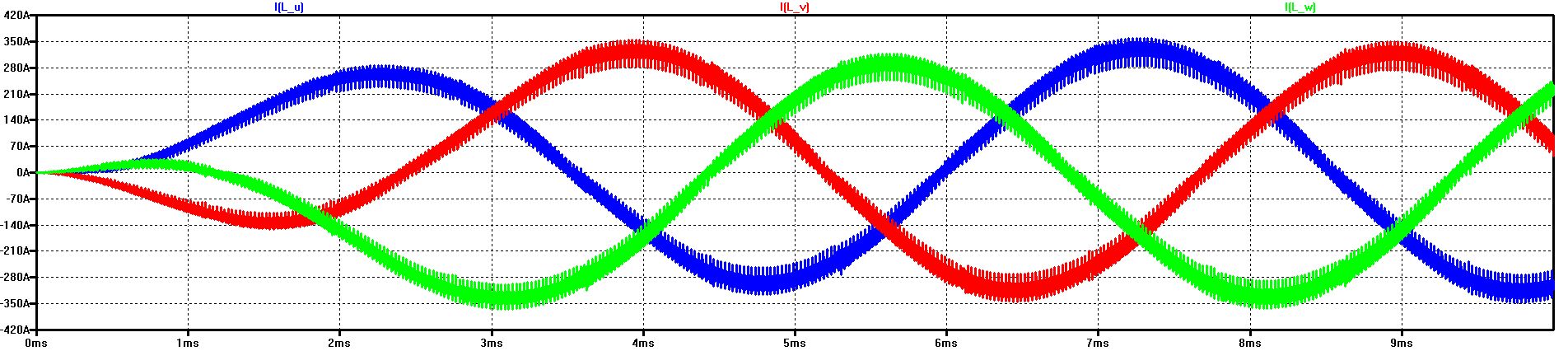
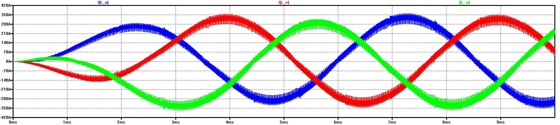
The diagram shows the start-up of the current in the 3 phases
After about 3 ms, a sufficiently steady state has been reached (the internal resistance of the HV voltage has been selected to be particularly high for this)
The shorter switching times cause higher spikes compared to the simulation with 10 kHz clock
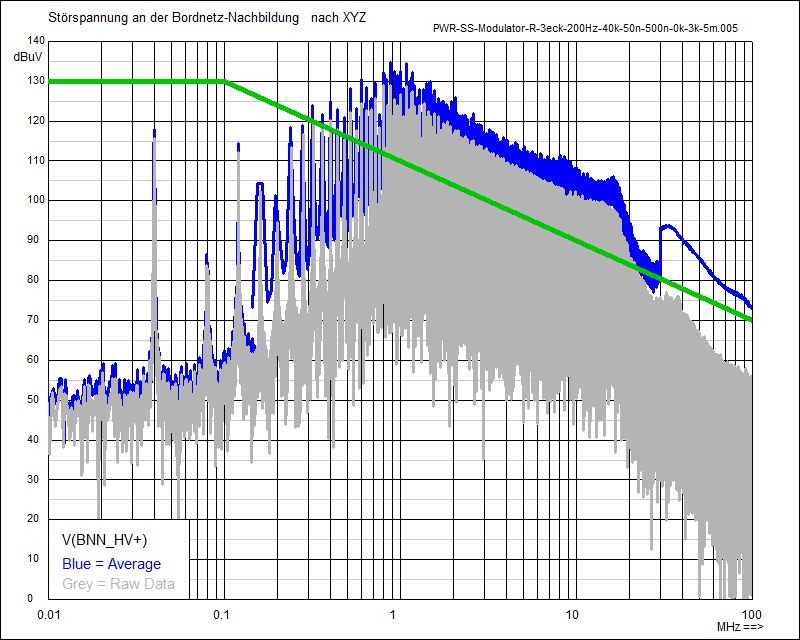
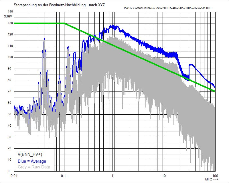
Noise Spectrum with fixed clock (40 kHz) at BNN (HV+)
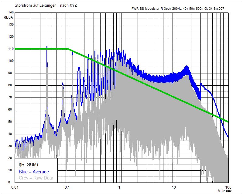
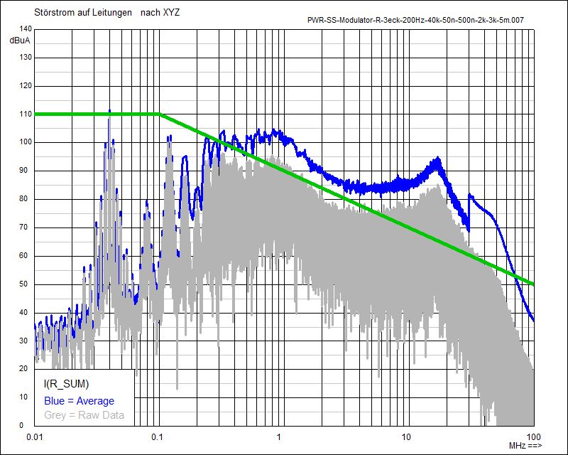
CM Spectrum of the Phase Currents with fixed clock (40 kHz)
Start-up of the current in the 3 phases with Spread-Spectrum Modulation (Delta-Frequency DSS = 2 kHz)
Compared to the phase current at a fixed clock, no significant difference in the current profile can be seen
Following shown are the noise spectra with Triangular Shift of the Clock, with Fixed Clock and with Random Shift:
Noise Spectrum with Triangular Modulation (2 kHz) at BNN (HV+)
CM Spectrum of the Phase Currents with Triangular Modulation (2 kHz)
Noise Spectrum with fixed clock (40 kHz) at BNN (HV+)
CM Spectrum of the Phase Currents with fixed clock (40 kHz)
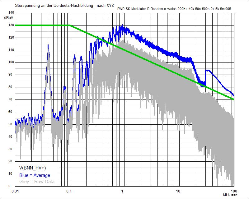
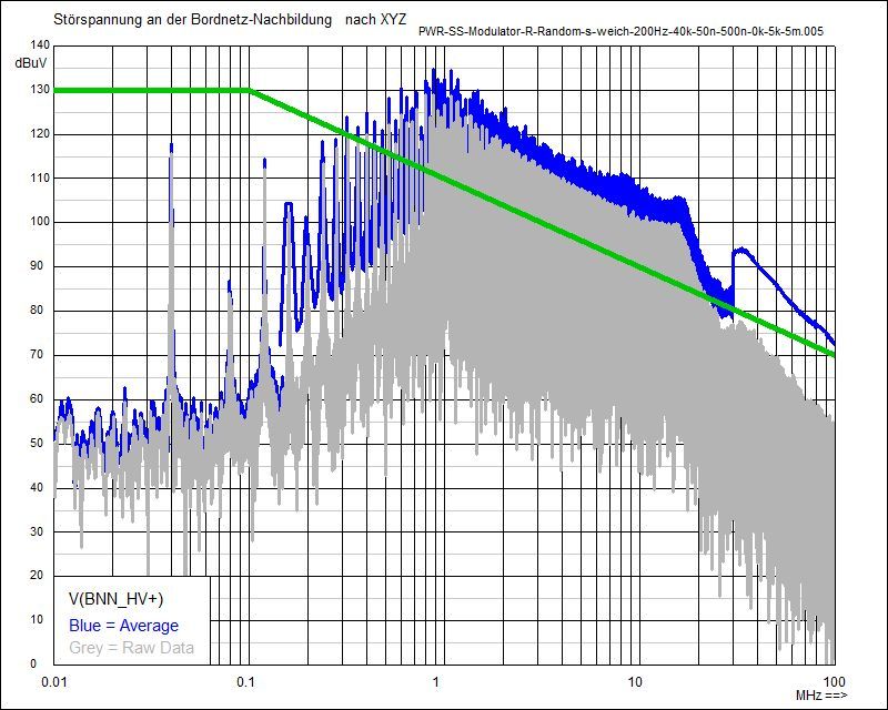
Noise Spectrum with Random Modulation (2 kHz) at BNN (HV+)
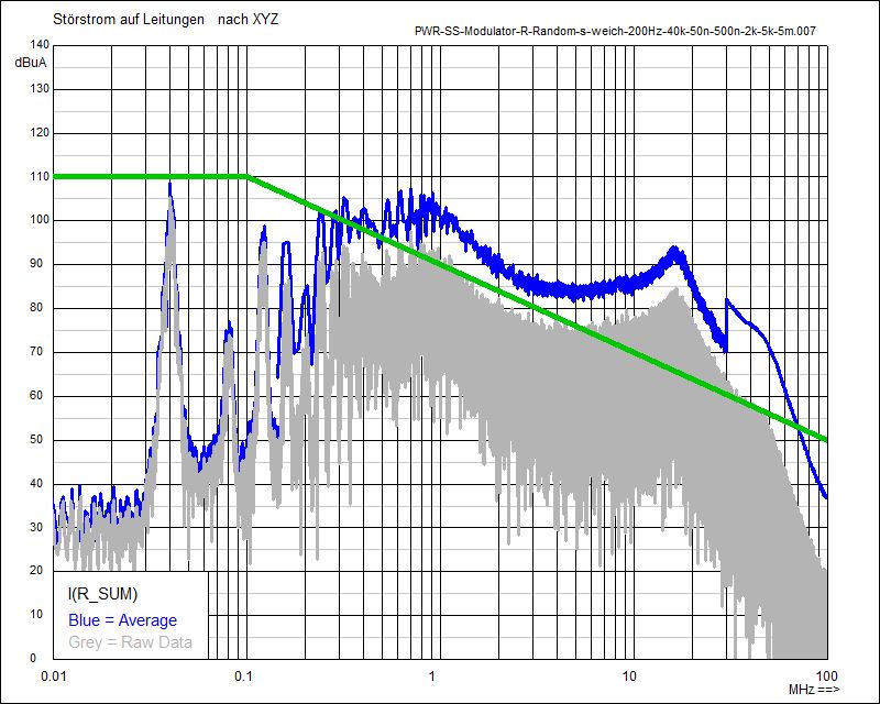
CM Spectrum of the Phase Currents with Random Modulation (2 kHz)
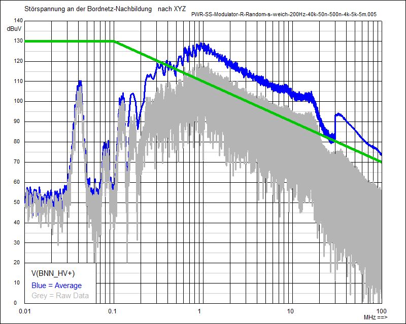
Noise Spectrum with Random Modulation (4 kHz) at BNN (HV+)
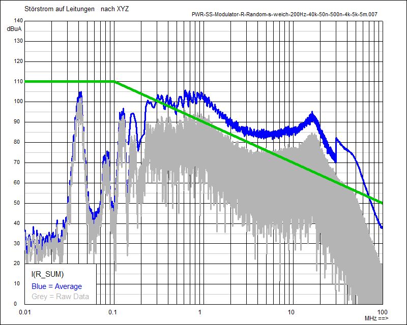
CM Spectrum of the Phase Currents with Random Modulation (4 kHz)

Noise Spectrum with fixed clock (40 kHz) at BNN (HV+)
CM Spectrum of the Phase Currents with fixed clock (40 kHz)
The wider spread of the spectral lines at 40 kHz clock is clearly visible. The higher clock frequency and the shorter switching times result in higher noise levels compared to the simulation with 10 kHz.
The Common-Mode Spectrum (CM) of the phase currents is similar to the spectrum on the HV-DC side. The current circuit for the switching spikes is closed via the capacitors in the artificial networks (BNN = LISN) to ground and the winding capacities of the motor emulation to ground.
Here too, the green limit curves serve only for better orientation and for easier comparison.
Simple inverter circuit (40 kHz clock) with Triangular Modulation (DSS = 2 kHz)
The Spread-Spectrum-Modulator is working here with Triangular Modulation and 2 kHz frequency shift of the clock - from 38 kHz to 42 kHz
The change of the frequency shifting is done with 3 kHz (FSS = 3k)
In contrast to the simulation with 10 kHz, there is a reduction in noise levels even above 150 kHz, with 40 kHz clock
Due to the wider spread of the spectral lines, overlapping areas are less - and thus there is also a reduction with a measuring bandwidth of 10 kHz
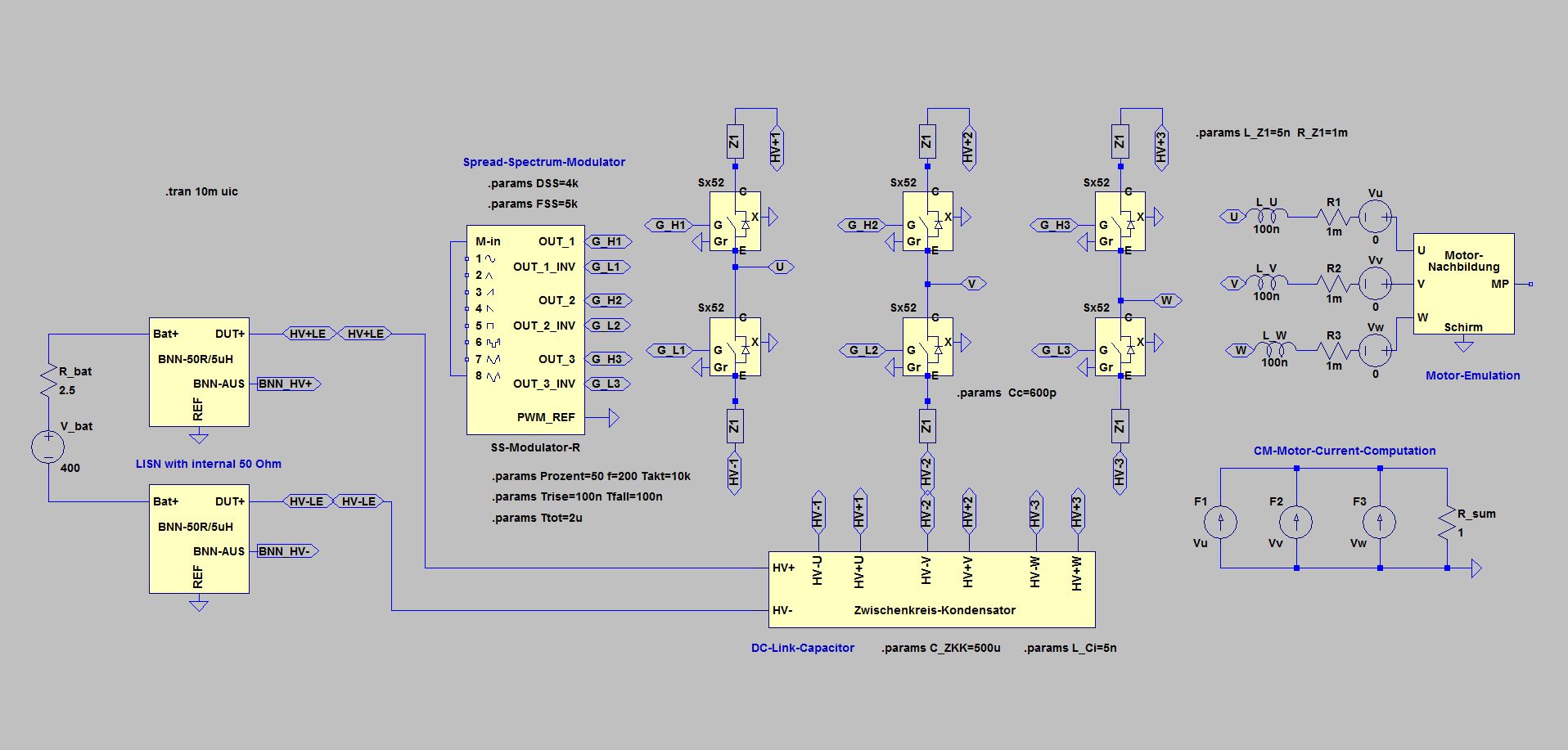
Simple inverter circuit (40 kHz clock) with Random Modulation (DSS = 4 kHz)
The Spread-Spectrum-Modulator is working here with Random Modulation and 4 kHz frequency shift of the clock - from 36 kHz to 44 kHz
The change of the frequency shifting is done with 5 kHz (FSS = 5k)
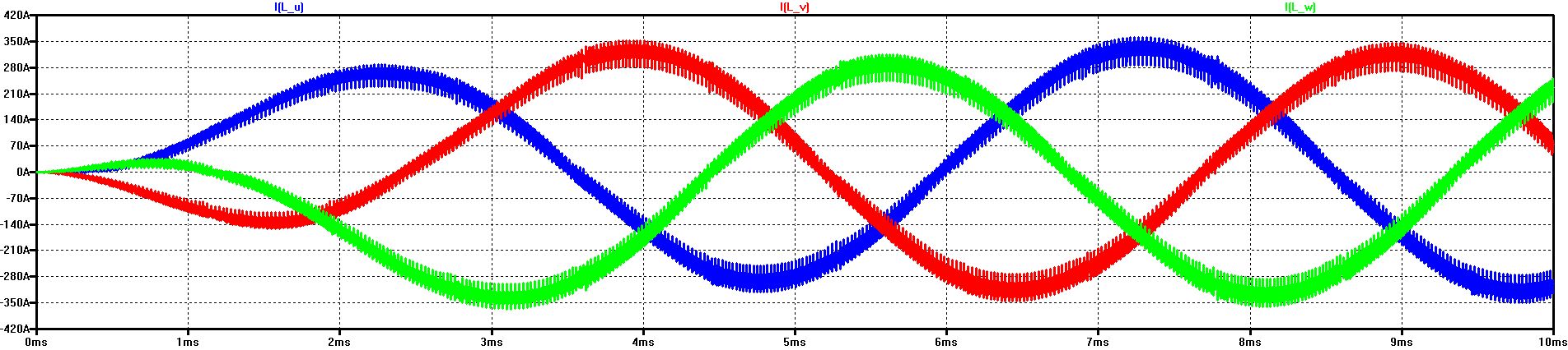
Start-up of the current in the 3 phases with Spread-Spectrum Modulation (Random Modulation, Delta-Frequency DSS = 4 kHz)
Compared to the phase current with fixed clock, there is no significant difference in the current characteristic even with a 4 kHz clock shift, because the relative shift is much lower at 40 kHz than at 10 kHz
Following shown are the noise spectra with Random Shift of the Clock, with Fixed Clock and with Random Shift:
Compared to the modulation with 2 kHz, the noise level in the lower frequency range up to 300 kHz is reduced even further with 4 kHz
Above 150 kHz, a slightly smoother course results from the larger shift and also a slightly lower noise level up to about 500 kHz. From there on there is no significant difference compared to 2 kHz.
© Ingenieurbüro Lindenberger 8447